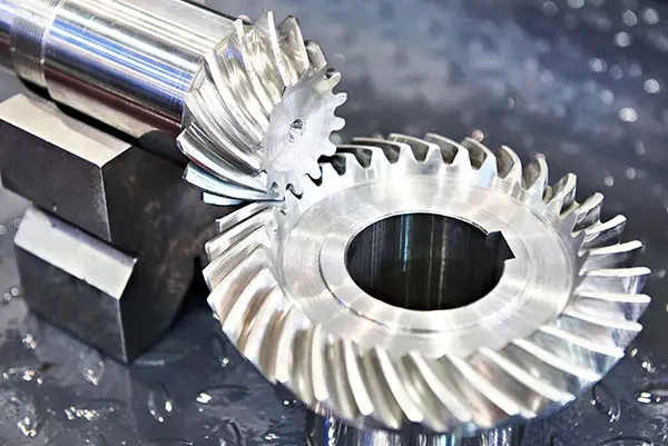
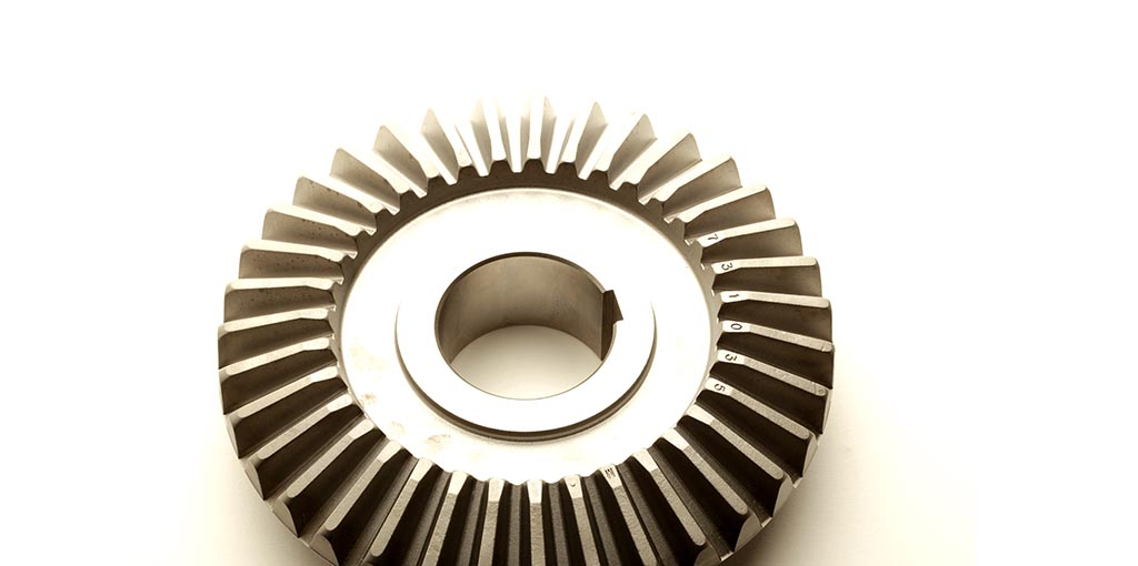
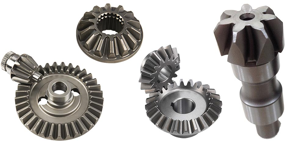
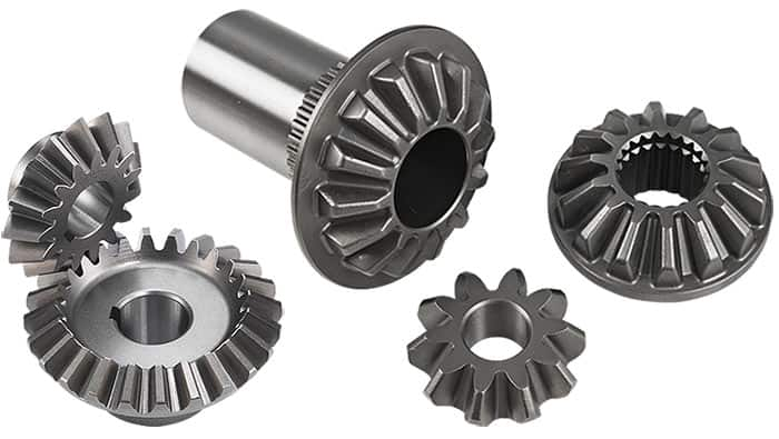
Bevel Gears
AmTech Manufacturing Solutions Guide Options
Our Handy solutions guide can help you determine what manufacturing process is right for your project or product.
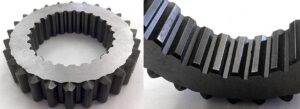
Bevel Gear Overview
Spiral Bevel Gear Capabilities
- Module Range: M2 to M15
- Maximum Outer Diameter: 600 mm
Zerol Bevel Gears
Materials
- 35
- S50C
- QT450
- 45#
- HT250
- S45C
- O8AI
Applications
- Automotive
- Construction
- Electrical
- Electronics
- Heavy Equipment
- Industrial Machinery
- Marine
- Medical Devices
- Off-Highway
- Pneumatics
Services
- Casting
- Climb Hobbing
- Conventional Hobbing
- Forging
- Grinding
- Heat Treating
- Honing
- Flame Cutting
- Lapping
- Milling
- Shaping
- Shaving
Dependable Gear Manufacturing
Precision Gear Manufacturing Solutions
Comprehensive Gear Manufacturing Capabilities
We produce a full spectrum of precision gears—including spur, helical, bevel, worm, ring & pinion, flywheels, flexplate assemblies, and specialty gears—using advanced hobbing, shaping, grinding, and heat treatment technologies. Our flexible production methods support both rapid prototyping and high-volume manufacturing, accommodating complex geometries and tight tolerances for demanding OEM applications.
Industry-Leading Experience & Quality
With over 25 years of specialized gear manufacturing expertise, AmTech guarantees exceptional accuracy, strength, and consistent quality in every gear. Our ISO 9001, IATF 16949, and QS 9000 certified processes and rigorous quality control ensure each gear meets your exact specifications and industry standards.
Global Supply Chain & Reliable Delivery
Our well-coordinated global manufacturing and logistics network enables us to overcome supply chain challenges and deliver precision gears on time, anywhere in the world. We support OEMs and industrial customers with dependable, scalable solutions and Just-In-Time (JIT) delivery from multiple warehouse locations.
Custom Engineering & Technical Support
AmTech’s engineering team collaborates closely with clients to design and optimize gears for specific applications. From material selection—including carbon steel, alloy steel, stainless steel, and specialty alloys—to gear geometry and finishing processes, we provide expert guidance and responsive support throughout every stage of your project.
Presentation
Download our Presentation
Get a deep dive into our capabilities with our detailed presentation
—your guide to precision engineering, quality assurance, and seamless production timelines.
Fill out the form to instantly download your copy and explore how we can elevate your projects!
Download Our Presentation
"*" indicates required fields
FAQ's
Frequently Asked Questions
What types of bevel gears does AmTech International manufacture?
Can you provide prototypes or small-batch bevel gears?
What materials are available for bevel gear manufacturing?
What industries use AmTech’s bevel gears?
How does AmTech ensure bevel gear quality and precision?
What is the maximum size and tolerance you can achieve for bevel gears?
Can AmTech assist with custom gear design and engineering?
How quickly can I get a quote or start a project?
Other Capabilities
Related Projects
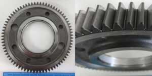
Truck Transmission Gear
AmTech manufactures this truck transmission gear for a OEM customer in the Semi-Truck
Transmission Spur Gear
This transmission spur gear is roughly the diameter of a large beverage can and weigh
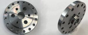
Supercharger Gear Hub
AmTech manufactures this steel gear hub for a large TIER 1 in the Automotive industry